


For details, see How to Use.
Vertex Array-Based Model Deformation Animation
This program is a VCSSL sample that animates the deformation of a model using a vertex array.
It is an advanced version of the following program:
How to Use
Download and Extract
At first, click the "Download" button at the above of the title of this page by your PC (not smartphone). A ZIP file will be downloaded.
Then, please extract the ZIP file. On general environment (Windows®, major Linux distributions, etc.), you can extract the ZIP file by selecting "Extract All" and so on from right-clicking menu.
» If the extraction of the downloaded ZIP file is stopped with security warning messages...
Execute this Program
Next, open the extracted folder and execute this VCSSL program.
For Windows
Double-click the following batch file to execute:
For Linux, etc.
Execute "VCSSL.jar" on the command-line terminal as follows:
java -jar VCSSL.jar
» If the error message about non-availability of "java" command is output...
Operations After Launch
When the program starts, a display window opens and a 3D surface begins to animate.
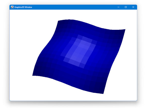
You can control the view with the following mouse operations:
- Left drag: Rotate the viewpoint
- Right drag: Move the viewpoint
- Mouse wheel scroll: Zoom in/out
Topic Overview
Modifying the Shape of a Model After Creation
This program builds on the one linked below. Since some of the explanations from that program are omitted here, please refer to it as needed:
In that previous program, we created and mounted a model from a vertex array. For static shapes, that's sufficient. However, in many cases you may want to modify the model's shape afterward.
In such cases, you can update the shape by assigning a new vertex array to the model. For example, in an animation, if you gradually update the vertex array at each frame and reassign it to the model, you can continuously deform its shape.
About the Vertex Array Format
The vertex array used for deformation must be in the same format as the one used to originally create the model.
In this program, we are using a model created with the Quadrangle Grid Mesh (QUADRANGLE_GRID) format, so we also use vertex arrays in the same format for deformation.
The Quadrangle Grid Mesh format represents a grid of quadrangles using a coordinate array indexed in both vertical and horizontal directions. For more details, refer to the earlier program linked above.
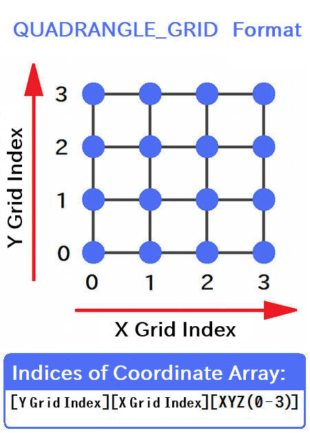
Assuming the grid lies in the X-Y plane (though it can also be in Y-Z or Z-X), the coordinates of each grid point are stored in a 3D float array structured as:
The first two indices represent the vertical and horizontal grid point positions (see the diagram), and the third index selects the X, Y, or Z coordinate of that grid point in space. The actual coordinate values are stored in this array.
Code
Full Code
Here is the complete code for this program:
coding UTF-8;

import Math;
import Graphics3D;
import graphics3d.Graphics3DFramework;


// Number of grid divisions in X and Y
const int X_N = 16;
const int Y_N = 16;

// Array to store vertex coordinates
float vertex[ Y_N ][ X_N ][ 3 ];

// Variable to store the model ID
int model;

// Time variable for animation
float time = 0.0;

// Amount of time change per frame
float timeStep = 0.1;


// This function is called once after the program starts
void onStart(int renderer){

	// Generate the model using the quadrangle grid format
	model = newModel(vertex, QUADRANGLE_GRID);

	// Set model color (red, green, blue, alpha)
	setModelColor(model, 0, 0, 255, 255);

	// Mount the model
	mountModel(model, renderer);
}


// This function is called continuously, several times per second
void onUpdate(int renderer){

	// Advance the time variable
	time += timeStep;

	// Calculate vertex coordinates
	for(int i=0; i<Y_N; i++){
		for(int j=0; j<X_N; j++){

			float x = j * 0.2;
			float y = i * 0.2;
			float z = 0.2 * ( sin( 2.0*x - time ) + sin( 2.0*y - time ) );

			vertex[ i ][ j ][ 0 ] = x;
			vertex[ i ][ j ][ 1 ] = y;
			vertex[ i ][ j ][ 2 ] = z;

		}
	}

	// Update the model with the new vertex array
	setModelVertex(model, vertex, QUADRANGLE_GRID);
}
In the following sections, we'll explain each part of the code in detail.
Header Section
At the top of the program, we import the standard libraries for mathematical functions (Math), 3D graphics (Graphics3D), and the 3DCG framework (graphics3d.Graphics3DFramework):
import Math;
import Graphics3D;
import graphics3d.Graphics3DFramework;
Declaring Global Variables
Next, we declare some global variables:
// Number of grid divisions in X and Y
const int X_N = 16;
const int Y_N = 16;

// Array to store vertex coordinates
float vertex[ Y_N ][ X_N ][ 3 ];

// Variable to store the model ID
int model;

// Time variable for animation
float time = 0.0;

// Amount of time change per frame
float timeStep = 0.1;
First, we declare the number of divisions (grid points) in the X and Y directions.
Then we declare the vertex array in a format compatible with the quadrangle grid mesh. We also declare a variable to store the model ID, as well as variables used to control the animation.
Implementing the onStart() Function
Now we implement the onStart() function. This function is automatically called once by the framework when the program starts.
// This function is called once after the program starts
void onStart(int renderer){

	// Generate the model using the quadrangle grid format
	model = newModel(vertex, QUADRANGLE_GRID);

	// Set model color (red, green, blue, alpha)
	setModelColor(model, 0, 0, 255, 255);

	// Mount the model
	mountModel(model, renderer);
}
In this function, we create a model using the QUADRANGLE_GRID format from the vertex array, then set its color to blue and mount it on the renderer (graphics engine).
For more detailed explanations of these steps, please refer to the earlier article:
Implementing the onUpdate() Function
Finally, we implement the core of this program: the onUpdate() function. This function is also called automatically by the framework -- but not just once. It is called repeatedly on every screen refresh (typically 30 times per second).
By setting slightly different vertex arrays on each call, we gradually deform the model, creating the illusion of animation -- much like a flipbook.
To reassign a vertex array to a model, we use the setModelVertex(...) function from the Graphics3D library. Here's how it's written in the program:
// This function is called continuously, several times per second
void onUpdate(int renderer){

	// Advance the time variable
	time += timeStep;

	// Calculate vertex coordinates
	for(int i=0; i<Y_N; i++){
		for(int j=0; j<X_N; j++){

			float x = j * 0.2;
			float y = i * 0.2;
			float z = 0.2 * ( sin( 2.0*x - time ) + sin( 2.0*y - time ) );

			vertex[ i ][ j ][ 0 ] = x;
			vertex[ i ][ j ][ 1 ] = y;
			vertex[ i ][ j ][ 2 ] = z;

		}
	}

	// Update the model with the new vertex array
	setModelVertex(model, vertex, QUADRANGLE_GRID);
}
First, we increment the time variable "time" by a small amount (timeStep).
Next, we update the contents of the vertex array to reflect the coordinates at that time. We use sine functions to create a wave-like shape, and incorporate the time variable into the sine arguments to make the shape move over time.
Finally, we call setModelVertex(...) to reassign the updated vertex array to the model. This is the point where the shape of the model actually changes.
License
This VCSSL/Vnano code (files with the ".vcssl" or ".vnano" extensions) is released under the CC0 license, effectively placing it in the public domain. If any sample code in C, C++, or Java is included in this article, it is also released under the same terms. You are free to use, modify, or repurpose it as you wish.
* The distribution folder also includes the VCSSL runtime environment, so you can run the program immediately after downloading.
The license for the runtime is included in the “License” folder.
(In short, it can be used freely for both commercial and non-commercial purposes, but the developers take no responsibility for any consequences arising from its use.)
For details on the files and licenses included in the distribution folder, please refer to "ReadMe.txt".
* The Vnano runtime environment is also available as open-source, so you can embed it in other software if needed. For more information, see here.
|
Simple Tool for Viewing and Converting Between RGB Values and Color Codes |
|
|
|
Display and Convert RGB Values and Color Codes on a GUI Tool |
|
A Simple Tool for Making Specific Colors Transparent (Batch Processing Version) |
|
|
|
Batch-Convert a Specific Color to Transparency in All PNG Files in a Folder |
|
A Simple Tool for Making Specific Colors Transparent |
|
|
|
Convert a Specific Color to Transparency in PNG Image Files |
|
Simple Tool for Animating Sequential Images |
|
|
|
A lightweight tool developed with VCSSL that allows you to play back sequential image files as an animation without converting them into a video file. |
|
Vertex Array-Based Model Deformation Animation |
|
|
|
How to Deform 3D Surface Models Using a Grid-Based Vertex Array |
|
Creating a Model from a Vertex Array (Quadrangle Grid Mesh Format) |
|
|
|
How to Create 3D Surface Models from a Grid-Based Vertex Array |
Black lines represent the edges of the quadrangles, and the blue dots are the grid points.
This kind of surface structure can be described entirely using the coordinates of the grid points. The coordinate array that does this is called the Quadrangle Grid Mesh (QUADRANGLE_GRID) format.