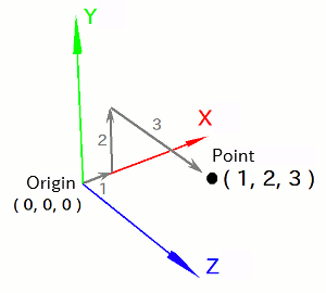
In this section, we'll cover the concept of coordinate systems -- an essential topic for creating dynamic 3D scenes -- as well as how to create and place them in a program.
The term coordinate system might sound intimidatingly mathematical, but VCSSL Graphics3D is designed to make working with coordinate systems intuitive and straightforward.
So far, when you've moved models or defined the positions of polygon vertices, you've specified a point in space using a set of three values: (X, Y, Z). This set of values is called a position vector, and the individual components are referred to as the X, Y, and Z components.
However, a position vector alone isn't enough to define a point in space -- it only gains meaning within the context of a coordinate system.
For example, the position vector (1, 2, 3) represents a point located by moving 1 unit in the X direction, 2 units in the Y direction, and 3 units in the Z direction from the origin -- that is, from the point (0, 0, 0). So in order to specify a point in 3D space, we need not just the X, Y, Z components of the vector, but also two reference elements: the position of the origin and the directions of the X, Y, and Z axes. Together, these form a coordinate system.

A position vector that points to a particular location in space will have different component values depending on the coordinate system.
Take the position vector (1, 2, 3) in one coordinate system. In another system, that same physical location in space might be represented by a different vector -- say, (0, 5, 3).
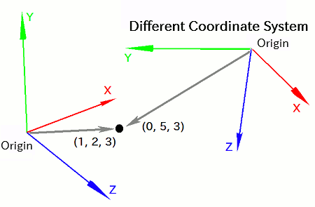
This discrepancy arises for two main reasons. First, the origin is located differently in each system -- meaning (0, 0, 0) points to different locations. Second, the directions of the X, Y, and Z axes may also differ. Even if the origins were aligned, the vector components would still differ due to this directional mismatch.
Coordinate systems are especially useful when you want to animate or move 3D objects.
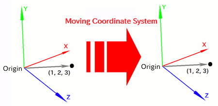
Let's say you place a model at the position (1, 2, 3) relative to a particular coordinate system. If you want to move the model, you don't need to modify its position directly -- you can just move the coordinate system itself. Since the model's position is defined *relative to the coordinate system*, the model will appear to move along with it.
Similarly, if you want to rotate the model, you can simply rotate the coordinate system. Because the X, Y, and Z axes themselves rotate, the point (1, 2, 3) also rotates accordingly, and the model appears to rotate.
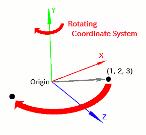
This is essentially an alternative to rewriting the position of the model directly -- instead, you move the reference frame itself.
Of course, it's still possible to move or rotate a model by directly modifying its position vector (1, 2, 3). In fact, that's exactly what the moveModel(...), movePolygon(...) and rotModel(...), rotPolygon(...) functions do internally.
However, if you want to move multiple models together, it's much easier to move a shared coordinate system than to update each model individually. For example, to move a "car," it would be tedious to move each component (wheels, body, driver) one by one. Instead, you can create a dedicated coordinate system for the car and place all its parts within it -- then just move the coordinate system to move the entire car.
Coordinate systems fall broadly into three categories:
The view coordinate system is a special coordinate system that stays fixed to the camera or "viewpoint" of the 3D scene. It's sometimes called the camera coordinate system.
Everything you see on the screen is a projection of 3D objects in the virtual space onto the XY plane of this view coordinate system, with perspective applied. This 2D projection plane is often referred to as the screen coordinate system.
From our real-world perspective, the view coordinate system can be thought of as one that's "stuck to your computer screen." In this sense, it's a bridge between the real world and the virtual one. Typically, the X-axis runs to the right, the Y-axis runs upward, and the Z-axis extends toward the viewer (although some systems use the opposite Z direction). This orientation remains constant even if the 3D world moves.
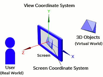
In addition to the view coordinate system, there's another important one: the world coordinate system. As the name suggests, this serves as the foundation of the entire 3D world.
While you could place models directly into the view coordinate system, doing so makes it difficult to manage the relative positions and orientations of objects when the camera moves. Every change in viewpoint would require you to recalculate the position and rotation of each object manually.
Instead, you can insert a world coordinate system between the view coordinate system and your models. This lets you move the camera by simply adjusting the relationship between the view and world coordinate systems, making things much easier to manage.
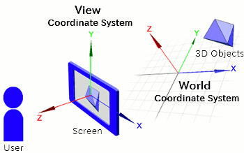
Another benefit of using the world coordinate system is that it allows you to define a consistent, camera-independent reference frame. This is especially useful in games or simulations where many moving objects must be coordinated. You can, for instance, define a ground-based reference for all movement and interactions.
Aside from the view and world coordinate systems, there are coordinate systems that you, the programmer, can create and use freely. These are generally called local coordinate systems. Typical use cases include moving an object dynamically or grouping multiple objects together to move them as one.
Local coordinate systems are not required by default, so you can declare and use as many as needed, based on your program's structure.
For example, imagine a 3D virtual world representing a city. Immovable objects like mountains can be placed directly in the world coordinate system. On the other hand, for moving objects like trains, buses, or airplanes, it's more convenient to create a dedicated local coordinate system for each one and place them there.
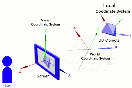
To create a general-purpose (local) coordinate system, use the "newCoordinate" function:
- Function Format -
This function creates a new coordinate system and returns a unique ID assigned to it.
Special coordinate systems like the world and view coordinate systems are automatically created and maintained by the renderer. These systems are also assigned IDs, which can be retrieved using the getWorldCoordinate(...) and getViewCoordinate(...) functions:
- Function Format -
The argument "rendererID" specifies the ID of the renderer.
The first function returns the ID of the world coordinate system, while the second returns the ID of the view coordinate system.
In VCSSL, coordinate systems are used by mounting them on top of other coordinate systems. The system being mounted onto is called the parent coordinate system, and the one being mounted is called the child coordinate system.
Coordinate systems can be layered in multiple levels, but the chain of parent systems must eventually trace back to either the world or view coordinate system.
To mount a coordinate system onto another, use the "mountCoordinate" function. For example, to mount a system onto the world coordinate system, use the following form:
- Function Format -
Arguments:
To mount a coordinate system onto another arbitrary (non-world) system, include one additional argument to specify the parent system:
- Function Format -
Arguments:
Let's try creating a local coordinate system and mounting it onto the world coordinate system. To make the difference visually clear, we'll place a small axis model on the local system, and a larger one on the world system. Try running the following code:
import graphics3d.Graphics3DFramework;
import Graphics3D;

// Function called at the beginning of the program
void onStart ( int rendererID ) {

	// Optional: Set the window size and background color
	setWindowSize( 800, 600 );
	setBackgroundColor( 0, 0, 0, 255 );


	// Create a local coordinate system
	int coord = newCoordinate( );

	// Mount the local coordinate system on the world coordinate system
	mountCoordinate( coord, rendererID );

	// Place a small axis model on the local coordinate system
	int axis1 = newAxisModel( 1.5, 1.5, 1.5 );
	mountModel( axis1, rendererID, coord );

	// Place a larger axis model on the world coordinate system
	int axis2 = newAxisModel( 3.0, 3.0, 3.0 );
	mountModel( axis2, rendererID );
}
When this program runs, you'll see two axis models on a black background. The smaller one is placed on the local coordinate system, while the larger one is placed on the world coordinate system.
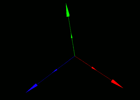
Now, if you move or rotate the local coordinate system, the small axis model mounted on it will move or rotate along with it. We'll cover how to perform these transformations next.

