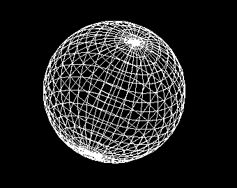
This section covers how to create and place polygons, as well as the various types of polygons available.
A polygon represents a small surface in 3D space and serves as the smallest fundamental unit that composes 3D shapes. In general, models are made up of multiple polygons, and especially for models with curved surfaces, a large number of polygons are used.

Strictly speaking, the term "polygon" means a multi-sided shape in English, and so it usually refers to triangles, quadrilaterals, and the like. However, in VCSSL Graphics3D, the definition is slightly extended -- any basic drawable element consisting of a set of vectors is referred to as a polygon. Therefore, in addition to triangles and quads, points, lines, and even basic drawable elements like characters and images are all called polygons.
To create a polygon, use one of the "new...Polygon" functions. The "..." part will be replaced by the name corresponding to a specific type of polygon. Various types of polygons exist, and the specific creation methods will be discussed in the next section.
- Function Format -
This function creates a polygon and returns its model ID.
You can also group multiple polygons together into a model using the newModel(...) function:
- Function Format -
For the "polygonID" argument, pass an array of IDs for the polygons that will make up the model.
This function bundles the given polygons into a single model and returns its ID. The advantage of turning a group of polygons into a model is that you can apply transformations such as translation and rotation to the entire group at once.
If you don't want to bundle a polygon into a model and just want to place it directly, use the mountPolygon(...) function.
- Function Format -
Arguments:
You can also specify a coordinate system for placement, as shown below. Coordinate systems will be explained later in this guide.
- Function Format -
Arguments:
Let's take a look at the different types of polygons and their creation functions.
Note: All functions explained below return the ID of the generated polygon.
A point polygon is a polygon used to represent a point. It's typically used for rendering tiny dots, but you can also use large point polygons as substitutes for spheres. While this approach lacks depth perception, it can significantly reduce rendering load.
To create a point polygon, use the newPointPolygon(...) function:
- Function Format -
Arguments:
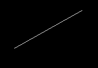
A line polygon is a polygon used to represent a straight line. You can draw not only thin 1-pixel lines but also thick lines with depth.
To create a line polygon, use the newLinePolygon(...) function:
- Function Format -
Arguments:
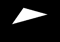
A triangle polygon is used to represent a tiny triangle. It's mainly used to form surfaces by connecting many of them together.
To create a triangle polygon, use the newTrianglePolygon(...) function:
- Function Format -
Arguments:
Triangle polygons have a front and back side. When the vertices A, B, and C are viewed in a counterclockwise order, that side is considered the front. Put another way, if you turn a right-hand screw in the order of A → B → C, the direction it moves forward in corresponds to the surface normal vector (the direction of the front face).
By default, triangle polygons are rendered only from the front side. If you view them from the back side, they appear invisible. You can make the back side visible by using the setPolygonCull(...) function.
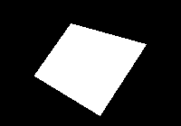
A quadrangle polygon is a polygon element used to represent a small quadrilateral. Like triangle polygons, it is typically used to form surfaces by connecting many such elements.
To create a quadrangle polygon, use the newQuadranglePolygon(...) function:
- Function Format -
Arguments:
Like triangle polygons, quadrangle polygons have a front and back face. When vertices A, B, C, and D appear in counterclockwise order from the viewer's perspective, that face is considered the front. In other words, if you rotate a right-hand screw along the order A → B → C → D, the direction the screw advances corresponds to the front-facing direction vector.
By default, only the front face is rendered. From the back side, the polygon appears invisible. To render both sides, you can use the "setPolygonCull" function to disable back-face culling.
An image polygon is a polygon used to display graphical data such as images or the rendered output of another renderer. Unlike texture mapping, image polygons are always rendered facing the screen.
To create an image polygon, use the newImagePolygon(...) function:
- Function Format -
Arguments:
Note that the "horizontalSize" and "verticalSize" are not measured in pixels or points, but in units of distance in 3D space.
By default, the image is drawn so that its lower-left corner aligns with the specified position. If you prefer to center the image on the position, you can apply an offset. Offsets allow you to shift text or image polygons in horizontal and vertical directions when rendering.
- Function Format -
Arguments:
Offsets are specified in 3D distance units, not in pixels.
A text polygon is a polygon used to display text. Text polygons are not rendered as 3D objects; rather, they always face the screen, making them ideal for annotations beside models.
To create a text polygon, use the newTextPolygon(...) function:
- Function Format -
Arguments:
The "size" is measured in 3D space units, not in pixels or points.
To change the font of a text polygon, use the setPolygonFont(...) function. Note that the available fonts depend on the environment.
- Function Format -
Arguments:
By default, the lower-left corner of the first character aligns with the specified position. To center the text instead, you can use the same offset adjustment method as with image polygons.
To apply offsets, use the setPolygonOffset(...) function:
- Function Format -
Arguments:
As with image polygons, offset values are specified in 3D space units, not pixels.
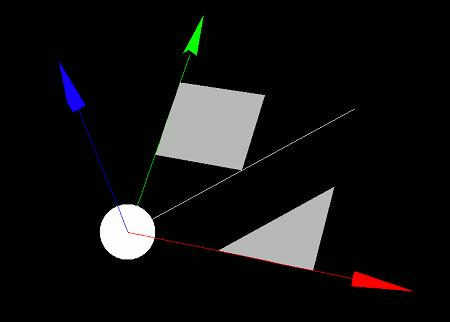
Now let's put the various polygons we've covered so far (excluding graphics and text polygons) into practice. Try writing and running the following program:
import graphics3d.Graphics3DFramework;
import Graphics3D;

// This function is called at the start of the program
void onStart ( int rendererID ) {

	// Optional: Set the window size and background color
	setWindowSize( 800, 600 );
	setBackgroundColor( 0, 0, 0, 255 );

	// Create and place the axis model
	int axis = newAxisModel( 3.0, 3.0, 3.0 );
	mountModel( axis, rendererID );


	// Create and place a point polygon
	int point = newPointPolygon( 0.0,0.0,0.0, 0.3 );
	mountPolygon( point, rendererID );

	// Create and place a line polygon
	int line = newLinePolygon( 0.0,0.0,0.0, 2.0,2.0,0.0 );
	mountPolygon( line, rendererID );

	// Create and place a triangle polygon
	int triangle = newTrianglePolygon(
			0.0,0.0,0.0,
			1.0,0.0,0.0,
			1.0,1.0,0.0
	);
	mountPolygon( triangle, rendererID );
	movePolygon( triangle, 1.0, 0.0, 0.0 ); // Translate position
	// setPolygonCull( triangle, false, false ); // Uncomment to render back face

	// Create and place a quadrangle polygon
	int quad = newQuadranglePolygon(
			0.0,0.0,0.0,
			1.0,0.0,0.0,
			1.0,1.0,0.0,
			0.0,1.0,0.0
	);
	mountPolygon( quad, rendererID );
	movePolygon( quad, 0.0, 1.0, 0.0 ); // Translate position
	// setPolygonCull( quad, false, false ); // Uncomment to render back face
}
When you run this program, various polygons will appear on a black background.
