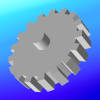
Polygon Mesh of a Sphere Model
A sphere model consists of a regular grid of rectangular polygons, much like the pattern formed by the meridians and parallels on a globe.
This section explains how to create and place 3D models, focusing on the various built-in standard models provided by VCSSL.
A model represents a three-dimensional shape, constructed from a collection of small polygons. You can think of it like a paper craft made of many flat pieces assembled into a 3D form.
For example, as shown above, a sphere model in VCSSL is made up of a large number of rectangles, arranged in a pattern similar to the lines of latitude and longitude on a globe. (*)
While you can generate your own custom polygon groups to build models in VCSSL, a variety of basic shape models are already available as standard.
In this section and those that follow, weÅfll focus on working with these standard models.
To create a standard model, use one of the "new...Model" functions, where "..." is the name of the specific model type.
- Function Format -
This function generates the specified model and returns a model ID that you can use to manipulate or place the model.
To create a model from your own collection of polygons, use the newModel(...) function. Polygon creation and manipulation will be covered in the next section.
- Function Format -
Arguments:
This function combines the specified polygons into a single model and returns its model ID. The advantage of grouping polygons into a model is that you can perform transformations like translation and rotation on the entire model at once.
The newModel(...) function can also be used to duplicate an existing model.
- Function Format -
Argument:
This will create a new model with the same shape as the one specified.
To place a model in the 3D scene, use the mountModel(...) function.
- Basic Function Format -
Arguments:
You can also specify a coordinate system for placement (coordinate systems will be covered later in this guide):
- Extended Function Format -
Arguments:
Now let's look at the various built-in standard models supported by VCSSL and how to create them.
All of the functions described below return a model ID as their return value.
The axis model is used to indicate directions in 3D space. You could say that setting up a 3DCG scene begins by placing this model -- it's a very important element for spatial reference.
To create an axis model, use the newAxisModel(...) function:
- Function Format -
Arguments:
To create a sphere model, use the newSphereModel(...) function:
- Function Format -
Arguments:
Note: The total number of polygons used will be n1 Å~ n2.
The more polygons used, the smoother the surface becomes; fewer polygons will make it appear more faceted. This model is placed such that its center (centroid) aligns with the origin of the coordinate system.
To create a box (rectangular prism) model, use the newBoxModel(...) function:
- Function Format -
Arguments:
This model is placed so that its center (centroid) aligns with the origin. Note that some libraries or languages may define the model such that a corner or face aligns with the origin, so be aware of this difference.
To create a cylinder model, use the newCylinderModel(...) function:
- Function Format -
Arguments:
This model is placed such that the center of its bottom face aligns with the origin.
To create an open-ended cylindrical (tube) model, use the newTubeModel(...) function:
- Function Format -
Arguments:
This model is also placed so that the center of its bottom face aligns with the origin.
To create a cone model, use the newConeModel(...) function:
- Function Format -
This model is placed so that the center of its base aligns with the origin.
To create an open-ended cone (shade-like) model, use the newShadeModel(...) function:
- Function Format -
Arguments:
This model is also placed so that the center of its base aligns with the origin.
To create a disk model, use the newDiskModel(...) function:
- Function Format -
Arguments:
The model is placed so that the center of the disk aligns with the origin.
Each polygon that forms a model has a front face and a back face.
By default, only the front faces are rendered -- back faces are omitted unless explicitly enabled. This technique is known as backface culling, and it's used to skip rendering surfaces that are not visible from the current viewpoint, reducing rendering cost and improving performance.
For example, the disk model described above has its front face pointing in the positive Z direction upon creation.
If you view it from the negative Z direction, the back face will be invisible due to culling. To make both sides visible, you can disable backface culling like this:
Here, "modelID" is the ID of the model you want to modify.
Now, let's try using the standard models introduced above. Write and run the following code:
import graphics3d.Graphics3DFramework;
import Graphics3D;

// The entry point of the program
void onStart ( int rendererID ) {

	// Optional: Set the window size and background color
	setWindowSize( 800, 600 );
	setBackgroundColor( 0, 0, 0, 255 );


	// Create and mount an axis model
	int axis = newAxisModel( 3.0, 3.0, 3.0 );
	mountModel( axis, rendererID );

	// Create and mount a sphere model
	int sphere = newSphereModel( 0.5, 0.5, 0.5, 10, 7 );
	mountModel( sphere, rendererID );

	// Create and mount a box model
	int box = newBoxModel( 1.0, 1.0, 1.0 );
	mountModel( box, rendererID );
	moveModel( box, 1.25, 0.0, 0.0 ); // Translate

	// Create and mount a cylinder model
	int cylinder = newCylinderModel( 0.5, 0.5, 1.0, 20, 1 );
	mountModel( cylinder, rendererID );
	moveModel( cylinder, 2.5, 0.0, 0.0 ); // Translate

	// Create and mount a tube (open-ended cylinder) model
	int tube = newTubeModel( 0.5, 0.5, 1.0, 20, 1 );
	mountModel( tube, rendererID );
	moveModel( tube, 0.0, 1.25, 0.0 ); // Translate
	// setModelCull( tube, false, false ); // Uncomment to show the inside surface

	// Create and mount a cone model
	int cone = newConeModel( 0.5, 0.5, 1.0, 20, 1 );
	mountModel( cone, rendererID );
	moveModel( cone, 1.25, 1.25, 0.0 ); // Translate

	// Create and mount a shade (open-ended cone) model
	int shade = newShadeModel( 0.5, 0.5, 1.0, 20, 1 );
	mountModel( shade, rendererID );
	moveModel( shade, 2.5, 1.25, 0.0 ); // Translate
	// setModelCull( shade, false, false ); // Uncomment to show the inside surface

	// Create and mount a disk model
	int disk = newDiskModel( 0.5, 0.5, 20 );
	mountModel( disk, rendererID );
	moveModel( disk, 0.0, 2.5, 0.0 ); // Translate
	// setModelCull( disk, false, false ); // Uncomment to show the back side
}
When you run this program, various standard models will appear on a black background.
Note that the inside surface of the tube model is considered a back face, so it is not rendered by default. To render the inside, remove the comment from the line "setModelCull(tube, false, false);" after creating the model. The same applies to the shade (open-ended cone) model and the disk model.