Up to this point, the rotations and spins of coordinate systems we've covered have involved incrementally rotating a system based on its current orientation. However, in some cases, you may want to directly control the orientation of a coordinate system. This section introduces how to do just that.
To describe the orientation of a 3D coordinate system, we need the concept of Euler angles. Euler angles express the posture of a coordinate system using three special angles.
There are various types and interpretations of Euler angles depending on the field or reference material, but here we will focus on the Z-X-Z Euler angles, which are commonly used in engineering.
Let the three angles used in the Euler angle system be denoted as α (alpha), β (beta), and γ (gamma). In the Z-X-Z Euler angle system, the orientation of a coordinate system is determined as follows:
This sequence defines the final orientation of the coordinate system.
Once you define values for α, β, and γ, the orientation of the coordinate system is uniquely determined.
However, the reverse is not always true. That is, a single orientation may correspond to multiple combinations of α, β, and γ. This means that Euler angles have certain orientations that they are not good at representing, and this can sometimes lead to unexpected issues. One of the most well-known problems related to this is the phenomenon called gimbal lock.
To avoid such issues, it's often better not to rely solely on Euler angles. Instead, you can use other methods such as the "rotCoordinate" and "spinCoordinate" functions, which allow rotation around arbitrary axes, depending on the situation.
To specify the orientation of a coordinate system using Euler angles, use the setCoordinateAngle(...) function:
- Function Format -
The parameters are as follows:
To obtain the Euler angles that represent the orientation of a coordinate system, use the getCoordinateAngle(...) function.
- Function Format -
The parameter "coordinateID" specifies which coordinate system to retrieve the orientation from.
This function returns an array of Euler angles (Z-X-Z system). The returned array contains:
As mentioned earlier, multiple Euler angle combinations can represent the same orientation. This function will return one possible combination, so keep in mind that the result is not necessarily unique.
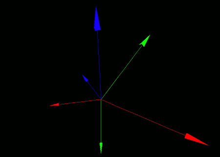
Let's place a local coordinate system within the world coordinate system, and make it spin like a top through animation. To make it visually clear, we'll attach a smaller coordinate axis model to the local system and a larger one to the world system.
import graphics3d.Graphics3DFramework;
import Graphics3D;
import Math;  // for using sin function


// Variable to store the ID of the coordinate system
int coord;

// Time counter (in frame update units)
int t = 0;


// Function called at the start of the program
void onStart ( int rendererID ) {

	// Optional: set window size and background color
	setWindowSize( 800, 600 );
	setBackgroundColor( 0, 0, 0, 255 );

	// Create a local coordinate system
	coord = newCoordinate( );

	// Mount it onto the world coordinate system
	mountCoordinate( coord, rendererID );

	// Attach a small axis model to the local coordinate system
	int axis1 = newAxisModel( 1.5, 1.5, 1.5 );
	mountModel( axis1, rendererID, coord );

	// Attach a large axis model to the world coordinate system
	int axis2 = newAxisModel( 3.0, 3.0, 3.0 );
	mountModel( axis2, rendererID );
}


//Function called multiple times per second to update the screen
void onUpdate (int renderer) {

	// Control orientation using Euler angles
	setCoordinateAngle(
		coord,
		0.08*t, 0.5*sin(0.03*t), 0.3*t
	);

	// Advance time counter
	t++;
}
When this program runs, you'll see coordinate axis models displayed on a black screen. The large axis is attached to the world coordinate system, and the smaller one to the local system.

The local coordinate system performs a complex motion resembling the precession of a spinning top.

