In this section, we'll explore how to implement practical camera movements.
VCSSL Graphics3D supports two main styles of camera control:
The simplest form of camera work involves rotating the world coordinate system placed on the view coordinate system in response to mouse input -- much like spinning a globe. We'll refer to this as *globe-style* camera work (*) here.
This approach is suitable when you want to view relatively small 3D objects from various angles.
Since this technique is extremely easy to implement (you just rotate the world coordinate system based on mouse input), we won't go into much detail here. In fact, the default camera behavior in the Graphics3DFramework already uses this globe-style camera work, so you don't need to implement it yourself.
Another commonly used approach, alongside the globe style, is to move the camera itself within the world coordinate system.
For example, in many 3D action games, the viewpoint is positioned slightly behind the protagonist, and the camera follows as the character moves. This camera-movement-style camera work is suitable for exploring large 3D environments while moving around.
This section focuses primarily on this camera-movement-style method.
The transformation from world coordinates to view coordinates is called the view transformation. Controlling the camera essentially means controlling this view transformation.
In general, coordinate transformations for 3D objects follow this sequence:
In globe-style camera work, the hierarchy of coordinate systems aligns directly with the order of coordinate transformations.
That is, a local coordinate system is mounted onto the world coordinate system, and the world coordinate system is (conceptually) mounted onto the view coordinate system.
As a result, the view transformation behaves the same as a regular transformation -- there's no difference. Camera control is handled just like any other coordinate system: you can move or rotate the world coordinate system using the moveCoordinate(...) and rotCoordinate(...) functions.
In contrast, camera-movement-style work involves mounting the view coordinate system onto the world coordinate system and then manipulating the view coordinate system itself.
This reverses the relationship between the coordinate hierarchy and the transformation order in the view transformation process. Because of this reversal, view transformations in this style require a slightly different approach than regular local or world transformations.
Fortunately, VCSSL Graphics3D provides dedicated functions for controlling this type of view transformation. Instead of using moveCoordinate(...) or rotCoordinate(...), you can use moveView(...) and rotView(...) to manipulate the viewpoint with the exact same intuitive feel as working with other coordinate systems.
To move the view coordinate system relative to the world coordinate axes, use the moveView(...) function.
- Function Format -
Arguments:
To move the view coordinate system relative to its own axes, use the walkView(...) function. This is essentially "walking" the view coordinate system in its own frame of reference.
- Function Format -
Arguments:
To rotate the view coordinate system around the world coordinate system's axes, use the rotViewX(...), rotViewY(...), rotViewZ(...), or rotView(...) functions.
- Function Format -
Each of these rotates the camera around the X, Y, or Z axis, respectively.
Arguments:
To rotate around an arbitrary axis direction, use the rotView(...) function:
- Function Format -
Arguments:
To specify both the direction and a reference point (endpoint) for the rotation axis, use the extended form of the rotView(...) function:
- Function Format -
Arguments:
To rotate the view coordinate system around its own axes -- that is, to make it spin in place -- use the spinViewX(...), spinViewY(...), spinViewZ(...), or spinView(...) functions.
- Function Format -
These functions rotate the view coordinate system around its own X, Y, or Z axis, respectively.
Arguments:
To spin the view coordinate system around an arbitrary axis direction (relative to itself), use the spinView(...) function:
- Function Format -
Arguments:
To specify both the direction and a reference point for the rotation axis, use the extended version of the spinView(...) function:
- Function Format -
To set the position (origin) of the view coordinate system, use the setViewLocation(...) function:
- Function Format -
Arguments:
To set the orientation of the view coordinate system using Z-X-Z Euler angles, use the setViewAngle(...) function:
- Function Format -
Arguments:
Let's try controlling the view coordinate system and simulate walking through a 3D scene, like in a game.
We'll implement a key input event handler so the camera can move using the arrow keys. Write the following code and try running it:
import graphics3d.Graphics3DFramework;
import Graphics3D;

// Function called at the start of the program
void onStart ( int rendererID ) {

	// Set window size and background color (optional)
	setWindowSize( 800, 600 );
	setBackgroundColor( 0, 0, 0, 255 );


	// Build a colorful 3D scene using box models

	int box1 = newBoxModel( 1.0, 3.0, 1.0 );
	mountModel( box1, rendererID );
	setModelColor( box1, 255, 0, 0, 255 );

	int box2 = newBoxModel( 1.0, 3.0, 1.0 );
	mountModel( box2, rendererID );
	setModelColor( box2, 0, 255, 0, 255 );
	moveModel( box2, 5.0, 0.0, 5.0 );

	int box3 = newBoxModel( 1.0, 3.0, 1.0 );
	mountModel( box3, rendererID );
	setModelColor( box3, 0, 0, 255, 255 );
	moveModel( box3, -5.0, 0.0, 5.0 );

	int box4 = newBoxModel( 1.0, 3.0, 1.0 );
	mountModel( box4, rendererID );
	setModelColor( box4, 255, 255, 0, 255 );
	moveModel( box4, 5.0, 0.0, -5.0 );

	int box5 = newBoxModel( 1.0, 3.0, 1.0 );
	mountModel( box5, rendererID );
	setModelColor( box5, 0, 255, 255, 255 );
	moveModel( box5, -5.0, 0.0, -5.0 );
}


// Event handler called when a key is pressed
void onKeyDown( int id, int keyCode ){

	// Get the renderer ID
	int rendererID = getRenderer();

	// Move forward/backward with UP/DOWN arrow keys
	if( keyCode == KEY_UP ){
		walkView( rendererID, 0.0, 0.0, -0.3 );
	}
	if( keyCode == KEY_DOWN ){
		walkView ( rendererID, 0.0, 0.0, 0.3 );
	}

	// Turn left/right with LEFT/RIGHT arrow keys
	if( keyCode == KEY_RIGHT ){
		spinViewY ( rendererID, -0.05 );
	}
	if( keyCode == KEY_LEFT ){
		spinViewY ( rendererID, 0.05 );
	}
}
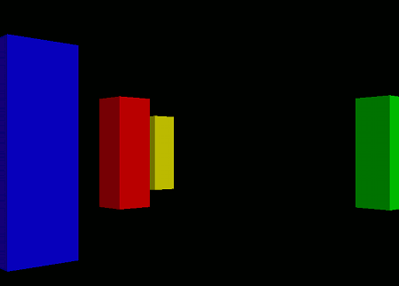
When you run this program, colorful buildings will appear on a black background. You can walk through the buildings using the arrow keys on your keyboard.


